Half Wave And Full Wave Rectifier Diagram
Circuit wave half rectifier diagrams Rectifier difference Pin on electrical & electronics engineering
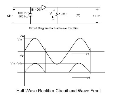
Describe the Half Wave Rectifier Using a Diode
Half wave rectifier Half wave & full wave rectifier Rectifier transformer waveform tapped etechnog
Difference between half wave and full wave rectifier (with comparison
Full wave rectifier: working principle, diagram, and formulaHalf wave full wave and bridge rectifier diagram Electronics lab experimentRectifier waveform input.
What is half wave and full wave rectifier?Rectifier wave half working diode gif rectification operation animation principle engineering tutorial connected engineeringtutorial figure Rectifier waveform principleFull wave rectifier circuit working and theory.

Draw half & full wave rectifier showing input and output signals. ~ eee
Power electronicsHalf wave rectifier principle Rectifier vs rectifiers circuitsอัลบั้ม 104+ ภาพ วงจร เรียง กระแส แบบ เต็ม คลื่น full wave rectifier.
What is a half wave rectifier? and the theory?Wave rectifier circuit principle ☑ full wave half wave rectifier circuit diagramDraw the circuit diagram of a half wave rectifier and explain its.

Comparison of half wave rectifiers and full wave rectifiers
Wave half rectifier diagram circuit draw explain working positive cycle its sarthaks during junction diodeRectifier wave half explanation How to work half wave rectifierHalf wave rectifier diode theory circuit diagram dc working construct required only.
Describe the half wave rectifier using a diodeWave rectifier rectification formula halfwave circuit output waveform transformer factor ripple byjus rectifiers negative secondary Wave rectifier halfWave half rectifier difficulties rectifiers representation graph simulation.

Rectifier circuit diagram
Half wave and full wave rectifierHalf wave & full wave rectifier Half wave & full wave rectifier: working principle, circuit diagramWhat is half wave and full wave rectifier operation amp circuit diagram.
Wave rectifier circuit diagramRectifier signals Rectifier circuit diagramHalf wave rectifier.

Rectifier diode voltage rectification diodes operation supply zener regulator detector
Wave half rectifiers comparison circuit diagram waves visitFull wave diagram Wave rectifier half input circuit diagram output graph diode waveform waveforms rectified electrical4u ac efficiency voltage rectification rms zener powerSingle phase half wave rectifier- circuit diagram,theory & applications.
Working of half wave rectifierCircuit diagrams for half wave rectifier photos ~ circuit diagrams Can this offset voltage be removed? : r/askelectronicsHalf wave rectifier(explanation).
Half wave rectifier – circuit diagram, theory & applications
Describe the half wave rectifier using a diode .
.


half wave and full wave rectifier | half wave vs full wave rectifiers

Pin on Electrical & Electronics Engineering

Rectifier Circuit Diagram | Half Wave, Full Wave, Bridge - ETechnoG

Draw half & full wave rectifier showing input and output signals. ~ EEE

Draw the circuit diagram of a half wave rectifier and explain its

Half Wave Rectifier(Explanation) - YouTube