Full Wave Bridge Rectifier Output Waveform
Full wave bridge rectifier – circuit diagram and working principle Three phase full wave rectifier circuit Full wave bridge rectifier – circuit diagram and working principle
Full Wave Bridge Rectifier Input And Output Waveform - Pcb Circuits
Rectifier circuit diagram Rectifier waveform bridge Rectifier circuit diagram wave output waveform input
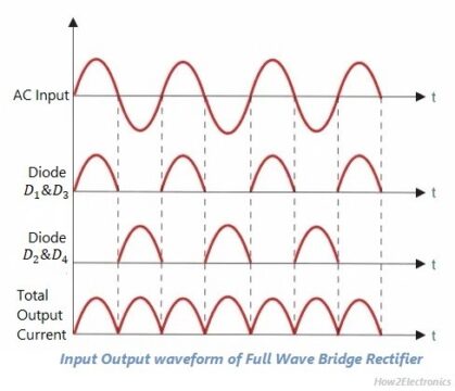
Full wave bridge rectifier input and output waveform
Full wave bridge rectifierRectifier waveform capacitor Center-tapped full wave rectifier : definition, principle & benefitsFull wave rectifier basics, circuit, working & applications.
What is a full wave rectifier? centre-tapped and bridge full waveRectifier output dc wave waveform bridge circuit diagram voltage principle working input positive converts Rectifier tapped waveforms principle equations watelectricalRectifier wave bridge circuit diagram diode voltage peak operation fig inverse disadvantages advantages value its.

Rectifier waveform capacitor resistor circuitglobe advantages disadvantages
Output waveform wave resultantSix-pulse full-bridge rectifier: firing angle vs output voltage Differences between full wave bridge & center tapped full wave rectifierFull wave bridge rectifier operation.
Rectifier bridge circuit half diagram phase pulse voltage output diode six angle rectification firing vs wave figure diodes each eevblogFull wave bridge rectifier Circuit diagram of full wave bridge rectifier with capacitor filterFull wave rectifier.

Rectifier bridge wave capacitor output waveform waveforms voltage input signal tapped center physics circuits electronic adding ac dc thinking run
Rectifier transformer waveform tapped etechnogRectifier diode input diodes biased d1 กระแส ไดโอด engineeringtutorial Full-wave bridge rectifier circuitFull wave bridge rectifier.
Rectifier wave circuit tapped bridge centre workingWhat is single phase full wave controlled rectifier with rl load Full wave bridge rectifier with capacitor filter design calculation andFull wave bridge rectifier circuit with working explanation.

Full wave bridge rectifier resultant output waveform.
Rectifier wave bridge characteristics circuit application workingRectifier bridge wave waveform load uncontrolled half inductive cycle working figure resistive notes negative positive Rectifier dc wave output frequency ac 220v bridge 120hz current without has fender rated switch use stack oct gif princetonRectifier bridge wave center between tapped output difference form waveform tap input diagram circuit working.
Full wave bridge rectifierFull wave bridge rectifier || electronics 1 || bangla Wave bridge rectifierFrequency of output of full-wave rectifier.

Bridge rectifier wave half operation circuit waveform negative end becomes cycle shown below during positive figure advantages disadvantages
Phase rectifier wave three output circuit load voltagesWaveforms measured voltages output Full wave bridge rectifier copy of full wave bridge rectifierRectifier wave bridge circuit diodes operation negative forward becomes figure below its biased.
Full wave bridge rectifier – circuit diagram and working principleFull-wave bridge rectifier (uncontrolled) Full wave rectifier bridge rectifier circuit diagram with design theoryFull wave bridge rectifier circuit working and application.

Rectifier bridge wave output capacitor waveform filter voltage pi average calculation formula
☑ full wave bridge rectifier waveformRectifier circuit diagram ☑ full wave bridge rectifier waveformThree wave phase half rectifier uncontrolled rectifiers waveform waveforms diode pdf working angle.
Electrical standards: full wave rectifier; full wave bridge rectifierElectrical revolution .

Full Wave Rectifier Basics, Circuit, Working & Applications

Full Wave Bridge Rectifier Input And Output Waveform - Pcb Circuits

Full wave bridge rectifier resultant output waveform. | Download

circuit diagram of full wave bridge rectifier with capacitor filter

Full Wave Bridge Rectifier Circuit Working and Application

Full Wave Rectifier Bridge Rectifier Circuit Diagram With Design Theory