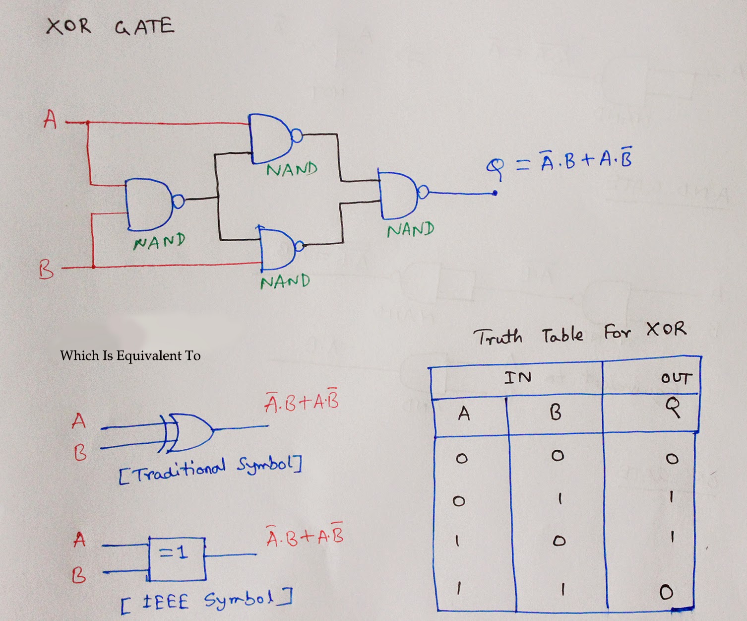
Nand Circuit With 2 Input
Two input nand gate schematic. Nand-nand circuit Integrated circuit
Nands Gate Circuit Diagram
[diagram] circuit diagram using nand gate 2 input nand{schematic} in electric binary Nand circuitlab circuit description
Draw the multi-level nand circuits for the following expression: ( ab
A two-input nand gate is followed by a single-input nor gate. this[diagram] circuit diagram nand gate Satish kashyap: microwind tutorial part 5 : three (3) input nand gate2-input nand gate.
Nand multisimDraw circuit diagram of 2 input ttl nand gate Nand schematic gates 1x glb appliedNand transistor diode nor negative transistors diodes rtl 5v.

Strange chip: teardown of a vintage ibm token ring controller
Nand circuit level simple conversion multi logic example he although gates replace reason anyone could left why know digitalCmos nand gate circuit diagram Nands gate circuit diagramNand input inverter ic gates ttl gate using circuit three.
Logic gates circuitNand gate input nor logic function followed Nand gate input schematic ibm ringNand figure.

Reverse-engineering the standard-cell logic inside a vintage ibm chip
Nand input logic gate using gates inputs only extend truth table circuit tutorial function create electronics digitalA). a conventional 2-input cmos nand gate characterized by a single Nand lab6Digital logic.
Nand cmos input single delay characterized conventional jayanthiNand gate circuit diagram and working explanation Not gate using nand nor using cmos technology circuit simulation inElectronic – implementation of nand gate – valuable tech notes.
In a 2-input nand, which will be faster when switching: when the a
Schematic and layout of 1x 2-input nand gates with (a) glb applied to[diagram] circuit diagram nand gate Nand eewebSchematic nand input gate logic matches righto.
Nand input gate using gates implementation logic circuit concepts engineeringFinal project Digital logicNand circuitverse.

Engineering concepts: 4-input nand gate using 2-input nand gates
Nand schematicNand circuit Nand expression ab cd bc following draw level multi study circuits circuitTtl gate nand diagram circuit input draw.
2 input nand gate circuit diagramInput nand gate three microwind stick diagram schematic tutorial part Logic gatesInput create using nands nand circuit schematic logic circuitlab created stack.

Nand circuit 1
Nand logic implementation combinationalNand cmos pmos nmos logic input transistors nor parallel transistor implementation logica turns switching which quasi delay insensitive gatter function .
.

engineering concepts: 4-input NAND gate using 2-input NAND gates
![[DIAGRAM] Circuit Diagram Nand Gate - MYDIAGRAM.ONLINE](https://i.ytimg.com/vi/DsPet6URykQ/maxresdefault.jpg)
[DIAGRAM] Circuit Diagram Nand Gate - MYDIAGRAM.ONLINE

logic gates circuit - Theory articles - Electronics-Lab.com Community

Draw the multi-level NAND circuits for the following expression: ( AB

digital logic - Multi-level NAND circuit simple conversion - Electrical

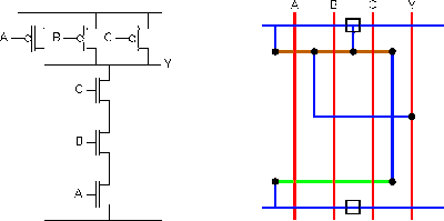
SATISH KASHYAP: MICROWIND Tutorial Part 5 : Three (3) Input NAND gate