Gray Code Counter Circuit Diagram
Flops sequence binary lecture Solved complete the design of the 3-bit gray-code counter Solved p3: 2-bit gray code counter is given in the following
Code Converter Circuit Diagram
Converter output Schematic diagram of designed gray code to bcd converter utilizing the Dual n-bit gray code counter style #2
2 bit gray code counter circuit
Counter asynchronous decade counters flip flop logic digital state pgt diagram timing clock flops output electronics realisation changes q0 firstCircuit counter diagram ic Counter gray code circuit simulatorCounter bit ve.
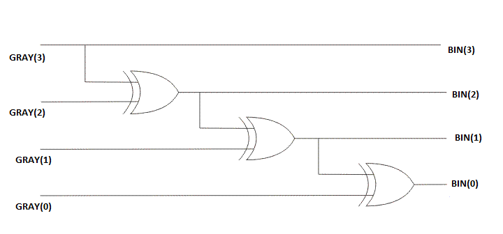
Verilog coding tips and tricks: 4 bit binary to gray code and gray codeCounter bit jk flip Gray counter code bit circuit waveformGray code counter.

Binary converter multisim
The circuit diagram of 4 bit binary to gray code converter4-bit gray code counter Counter gray bit code synchronous flip using flops show advance thanks please work counting enable input solved transcribed textCounter circuit.
17. the bcd (mod10) synchronous up counter circuit constructed with dCode gray binary bit converter verilog circuit coding logic tricks tips 13+ counter circuit diagramSimple counter circuit diagram.

Code converter circuit diagram
🎉 gray code example. what is gray code?. 2019-02-28Gray counter 3 bit gray code counter using jk flip flopSolved design a 3-bit gray code counter using jk flip-flops..
Design a 3-bit gray code counter using jk flip flopsSolved: chapter 7 problem 4e solution Bcd converter nor schematic utilizingBinary to gray code converter.

Counter circuitry
Binary converter circuitverseVerilog: implementing a 4 bit counter using d flipflop.in verilog Gray code counter circuit diagramCounter circuit simple diagram microcontroller pic using wiring programming assembly creating language.
Gray code example binaryCounter gray bit code state diagram solved p3 given transcribed problem text been show has Gray counter code circuitverse bitCounter universal.

4-bit gray code counter
Counter bit gray code diagram state consider figure2 bit gray code counter verilog code Gray code counter (4 bit)- gray code circuit- gray code waveformStevenson deckel rekrutieren 4 bit counter t flip flop durch kontur.
Design a 3-bit gray code counter using d-flip-flopsDesign a 3-bit gray code counter using jk flip flops Gray code counter circuit bitGray code counter/memory circuitry..
Virtual labs
Digital logicSolved: design a synchronous 2-bit gray-code counter with Counter synchronous bcd mod10 flip flops constructed.
.


Verilog: Implementing a 4 bit counter using D flipflop.in Verilog

Solved: Design A Synchronous 2-bit Gray-code Counter With | Chegg.com

Solved Complete the design of the 3-bit Gray-Code counter | Chegg.com

3 Bit Gray Code Counter Using Jk Flip Flop

2 bit gray code counter verilog code - keenver

13+ Counter Circuit Diagram | Robhosking Diagram